It started off as yet another elective course, where I had to prototype a smart object using the equipment of my school’s fab lab (site is Dutch). But it rapidly got out of hand as I got excited about my idea. So I decided to write a post about the adventure.
The idea included a game controller using capacitive touch sensors as its only input. The smart thing about it, is that it is able to sense whether your holding the controller or not. I got the idea for the capacitive sensors from a video I stumbled upon, demonstrating a capacitive sensing library for Arduino. Because I’m into games, making a game controller out of these sensors was a small step in the thought process. After a week or so, I came with the idea of using a more sensitive sensor which would be used to check if the controller is being held. I thought this might be useful in pausing and unpausing a game. This means that when you pick up the controller you’ll resume the game and when you lay down the controller (or accidentally drop it), the game will pause. Meanwhile I started working on the design of the controller. It took me three revisions to come to the following result.
The Design
The first version of the design had some sharp handles sticking out. But I decided to cut these off in the 3D model, to cut on the costs of printing. So I came to a second version. I was then advised to cut the body into smaller parts, because the DIY 3D printers tend to have issues once in a while. That’s why I separated the body in to two halves. Also, I added a little bump to each touch pad, so the player could feel where the centre of the pad is. This became the final design.
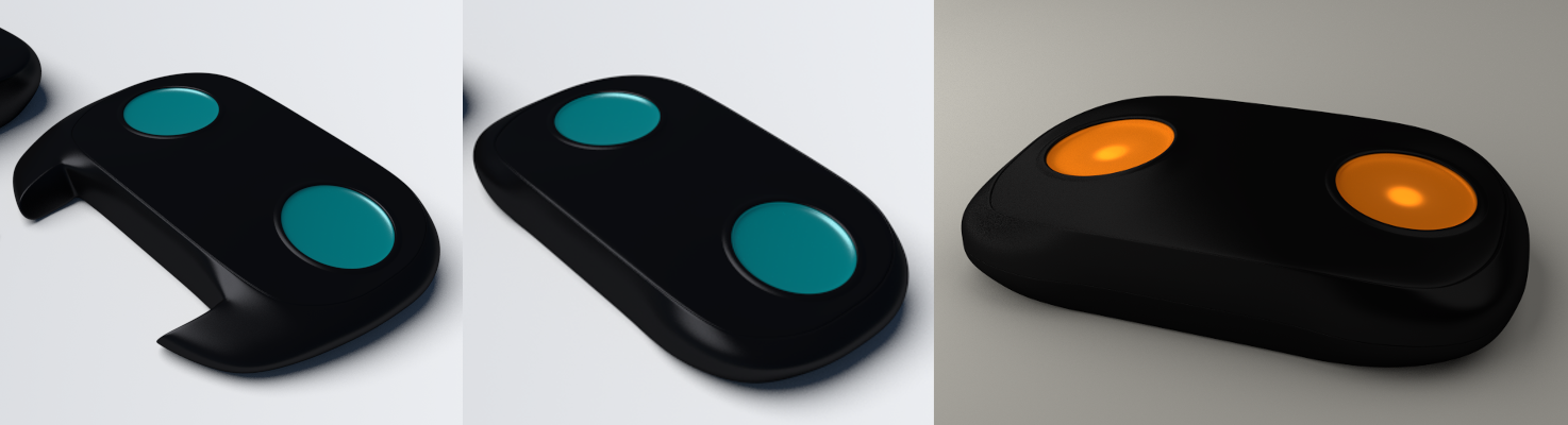
The design for the controller is inspired by the Steam Controller and a bit by the SNES controller. It consists of six parts. From top to bottom you have the cover (1), two touch pads (2), the upper half of the body (3), the lower half of the body (4) and a slide cover (5) to secure the Arduino inside the housing (see image below).

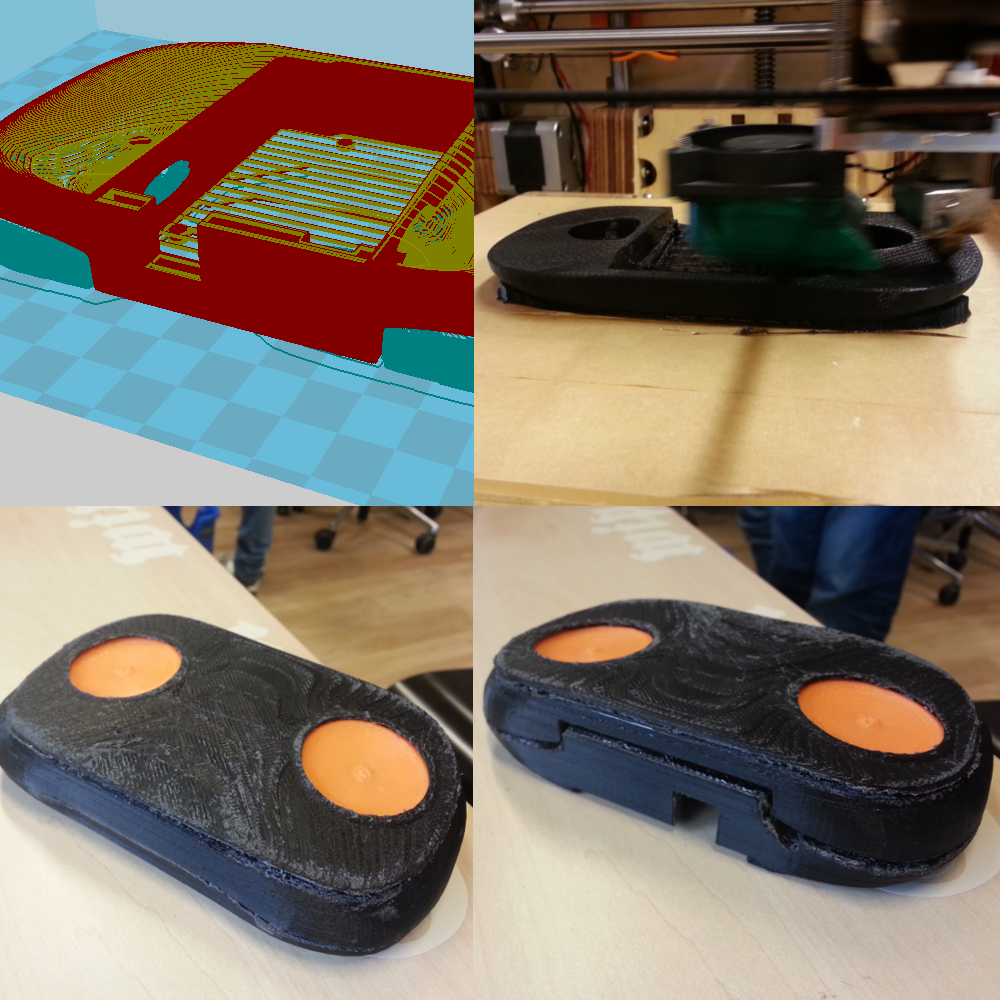
I tried 3D printing all parts using the available 3D printers. I started with the smaller parts so I could practise a bit on printing and find the best printer configuration. When I was familiar with printing the small parts, I started printing the upper half and lower half of the body. The filling of the inside of these parts were set too high. So they took around four to five hours each to complete. The touch pads were the most important parts of the prototype, so I decided to print them once more with a better printer configuration. Because the printing material couldn’t be switched easily for a different coloured one, the touch pads became orange and the body black. I must say, I’m quite happy with the colours as they are now. But the printed parts didn’t fit too well. I had to cut away some of the material to make everything fit. Also, I had a lot of waste, because of all the support that was printed.
Technical Design
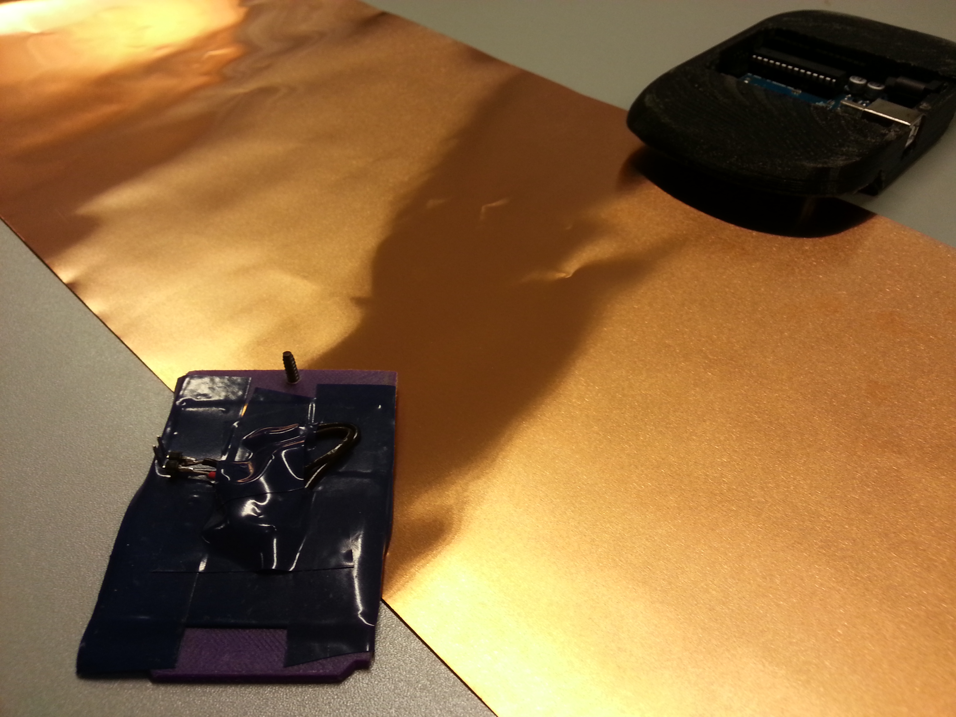
To make the controller work, I started experimenting with the touch sensors using the capacitive sensing library. First I did a test where I turned on a LED by touching a piece of aluminium foil. For this experiment I used the example code from the web page of the library to measure whether the foil was touched. The next thing I did, was experimenting with different placements and shapes of aluminium foil for creating the final touch pads. According to the tests, individual placed sensors would be the easiest choice and would give the best results.

After these tests I started building the sensors. Soon, I discovered aluminium foil wasn’t very nice to work with. Soldering the aluminium foil left burn marks on the foil and it wrinkled easily. So I decided to get myself some proper material – copper foil. Copper foil is stronger (depending on the thickness), thus easier to work with, and it conducts around 40% more then aluminium foil. After I got the copper foil, I started making the long distance sensor, which was easier to make then the other touch sensors. This sensor was then stuck on to the back of the slide cover with insulating tape. Although… the slide cover wasn’t sliding any more. Instead, I had drilled a hole in the cover. There was no other choice, because of all the cables underneath the cover, coming out of the Arduino. And the body didn’t have the correct measurements to fit the slide cover.
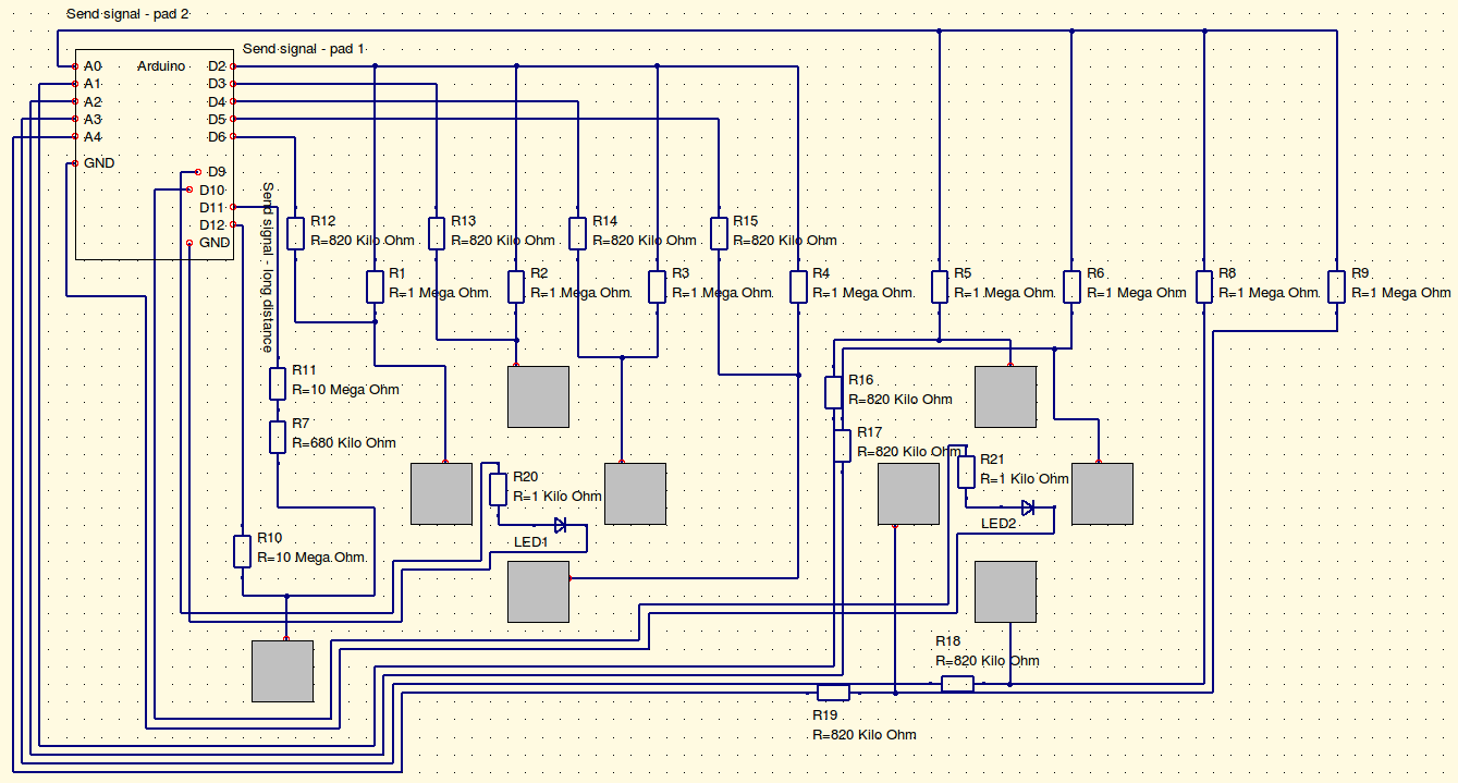
The following two things on the list were the actual touch pads. Basically, each touch pad was a set of cables and resistors mingled together, with at each end of a red wire a piece of copper foil. After the soldering, there was some glueing to be done. I super glued a bright, white LED to each of the printed parts, followed by the copper sensor ends.

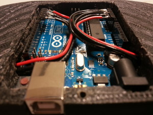
Once the touch pads were completed, I placed them in the housing. This was the most tricky part, because the cables had to go through small holes and needed to be bent in a way it could fit in the housing.
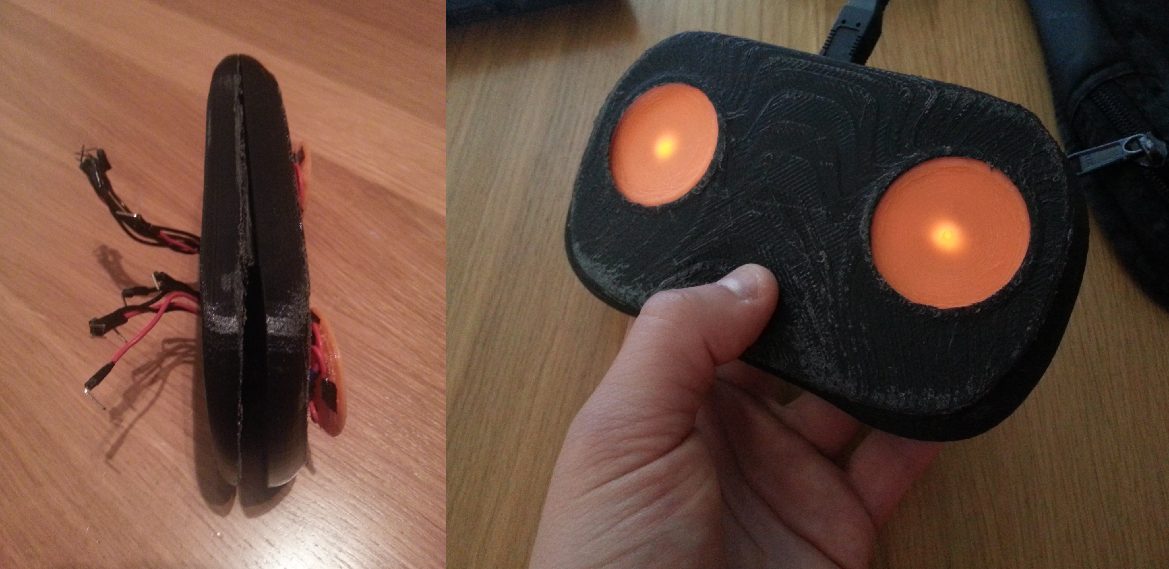
I connected all the cables and tested it. When testing the LEDs, I discovered that you could easily change the intensity of a LED. So, besides that the LEDs make the whole thing more fancy, I added some lines of code to let them give the user feedback of the user’s actions. Using a arbitrary scale, the table below shows how the LEDs give the user the proper feedback.
|
Action |
Brightness LED left |
Brightness LED right |
| Controller is connected to a device (pc) |
1 |
1 |
|
User holds the controller |
2 |
2 |
|
Button on the left touch pad is being touched and the user is holding the controller |
3 |
2 |
|
Button on the right touch pad is being touched and the user is holding the controller |
2 |
3 |
Demo time!
Here’s a video demonstrating the prototype so far.
The next steps
As shown in the video, not all the sensors work perfectly. To make all the sensors work, I might have to experiment with using a ground plane beneath the sensors. Also, when connected, the Arduino isn’t seen by the PC as a proper joystick yet. But I found some resources on the web, showing me how to do this. Unfortunately, I don’t have the time and resources to make this happen right now. Perhaps in the near future – I’m not sure. But you don’t have to wait for me to start tinkering yourself. If you’re interested in any way, you can download the 3D model and modify the code as you wish. If you’re planning on using my work, an attribution is appreciated. Also, feel free to comment on this post.

Capacitive Touch Game Controller (files) by Dylan Dophemont is licensed under a Creative Commons Attribution 4.0 International License.
- The Arduino code
- Blend file of the 3D model
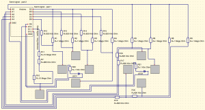
- Schematic